20+ deployment diagram example
20 Common Project Risks These are the 20 common project risks which we have included in the risk register along with suggested mitigating actions and contingency actions. You can edit this template and create your own diagram.
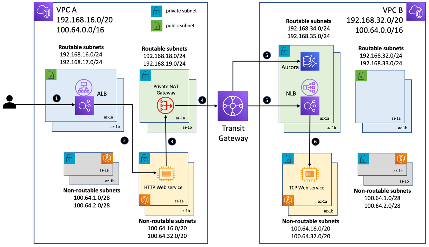
Addressing Ipv4 Address Exhaustion In Amazon Eks Clusters Using Private Nat Gateways Containers
Configuration Examples for USB-based Deployment.

. This is in contrast to continuous deployment which uses automated deployments. A multivalued attribute can have more than one value. For example you may be performing better in terms of battery life give yourself a 4 but worse in lightweight design a 2.
Creating a mapping follows a standard process which can vary depending on the use case. Creately diagrams can be exported and added to Word PPT powerpoint Excel Visio or any other document. Telephone Use of Association Class Diagram Example.
A project schedule network diagram is an output type of the process sequencing activities according to PMIs Guide to the Project Management Body of Knowledge PMBOK 6 th ed ch. The client portion shall require less than 20 MB disk space and 32 MB RAM. Figure 6-8 Networking diagram for configuring Telnet login.
Running the preceding command resets the LOM to the factory default settings and deletes all the SSL certificates. GoF Design Patterns - Abstract Factory. This section is organized by physical network configuration.
The rate of deployment changes. Class Diagram Realization Example. For example an employees social security number might be the employees key attribute.
A binary signal restricted to only 2 states. Example for Configuring USB-based Deployment Using a smart_configini Index File. When namespace isolation is enabled a single Istiod instance can support 1000 services 2000 sidecars with 1 vCPU and 15 GB of memory.
You can add notes on a activity using the commands note left note right note top or note bottom just after the description of the activity you want to note. Use PDF export for high quality prints and SVG export for large sharp images or embed your diagrams anywhere with the Creately viewer. The rate of configuration changes.
Telnet_Server-ui-vty0-14 history-command max-size 20 Set an authentication mode for the VTY user interface. This is the next installment in a series of articles about the essential diagrams used within the Unified Modeling Language or UML. For instructions on how to reconfigure the LOM port see Lights out management port of the Citrix ADC MPX appliance.
Project purpose and need is not well-defined. A derived attribute is based on another attribute. Project schedule network diagrams show the order in which activities should be scheduled to address logical relationships between these.
For example Runnable is. Below is an example deployment diagram. In the LOM GUI navigate to Configuration SSL Certification and add a certificate and private key.
SCSI 10 Paravirtual 20 CRS and voting disk CRS2 VMDK Hard disk 3 Shared disk devsdc1 SCSI 11 Paravirtual 20 CRS and voting disk CRS3 VMDK Hard disk 4 Shared disk devsdd1 SCSI 12 Paravirtual 20 CRS and voting disk VMFSDATA01 VMDK Hard disk 5 Shared disk devsde SCSI 13 Paravirtual 300 RAC database DATA. A component diagram also known as a UML component diagram describes the organization and wiring of the physical components in a system. Technical evaluation on a one to five scale.
If you want to put a note on the starting point define the note at the very beginning of the diagram description. Get More Component Diagram Templates Deployment Diagram. Project schedule is not clearly defined or understood.
You can increase the number of Istiod. In Red Hat Enterprise Linux RHEL 8 the userspace utility program iptables has a close relationship to its successor nftablesThe association between the two utilities is subtle which has led to confusion among Linux users and developers. An analog signal is continuous and the values are linearly interpolated between the given setpoints.
In my previous article on sequence diagrams I shifted focus away from the UML 14 spec to OMGs Adopted 20 Draft Specification of UML UML 2In this article I will discuss Structure Diagrams which is a new diagram category that. A deployment diagram shows the hardware of your system and the software in that hardware. While a use case itself might drill into a lot of detail about every possibility a use-case diagram can help provide a higher-level view of the system.
Academic literature differentiates between the two approaches according to deployment. Project design and deliverable definition is incomplete. For example an employees monthly salary is based on the employees annual salary.
A clocked signal that repeatedly transitions from high to low with a period and an optional pulse and offset. Using the logical diagram of the mapping editor you can construct your mapping by dragging components onto the diagram dragging connections between the components dragging attributes across those connections and modifying the properties of the components. For example an employee entity can have multiple skill values.
Each such configuration is illustrated by a deployment diagram followed by a mapping of processes to each processor. However this part is inherently horizontally scalable. The number of proxies connecting to Istiod.
Deployment diagrams are useful when your software solution is deployed across multiple machines with each having a unique configuration. Due to their simplistic nature use case diagrams can be a good communication tool for stakeholdersThe drawings attempt to mimic. A simplified concise signal designed to show the movement of data great.
Continuous delivery is the ability to deliver software that can be deployed at any time through manual releases. Component diagrams are often drawn to help model implementation details and double-check that every aspect of the systems required functions is covered by planned development. For example for a simple e.
What Is a Project Schedule Network Diagram. In this article I attempt to clarify the relationship between the two variants of iptables and its successor program nftables. It has been said before that Use case diagrams are the blueprints for your system.
According to Martin Fowler continuous deployment requires continuous delivery.

Fugle Innovation Process Model 20 Download Scientific Diagram

Starbucks Competitive Profile Matrix Matrix Business Strategy Horizontal Integration

20 Flow Chart Templates Design Tips And Examples Venngage

El Ciclo De Desarrollo De Una App Infografia Infographic Software Tics Y Formacion Ingenieria De Software Lenguaje De Programacion Infografia
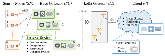
Sensors Free Full Text Smart Parking System With Dynamic Pricing Edge Cloud Computing And Lora Html

Addressing Ipv4 Address Exhaustion In Amazon Eks Clusters Using Private Nat Gateways Containers

Installation Guidelines Octopus Deploy

An Example Of An Ml System Processing A Linear Regression Task I E Download Scientific Diagram
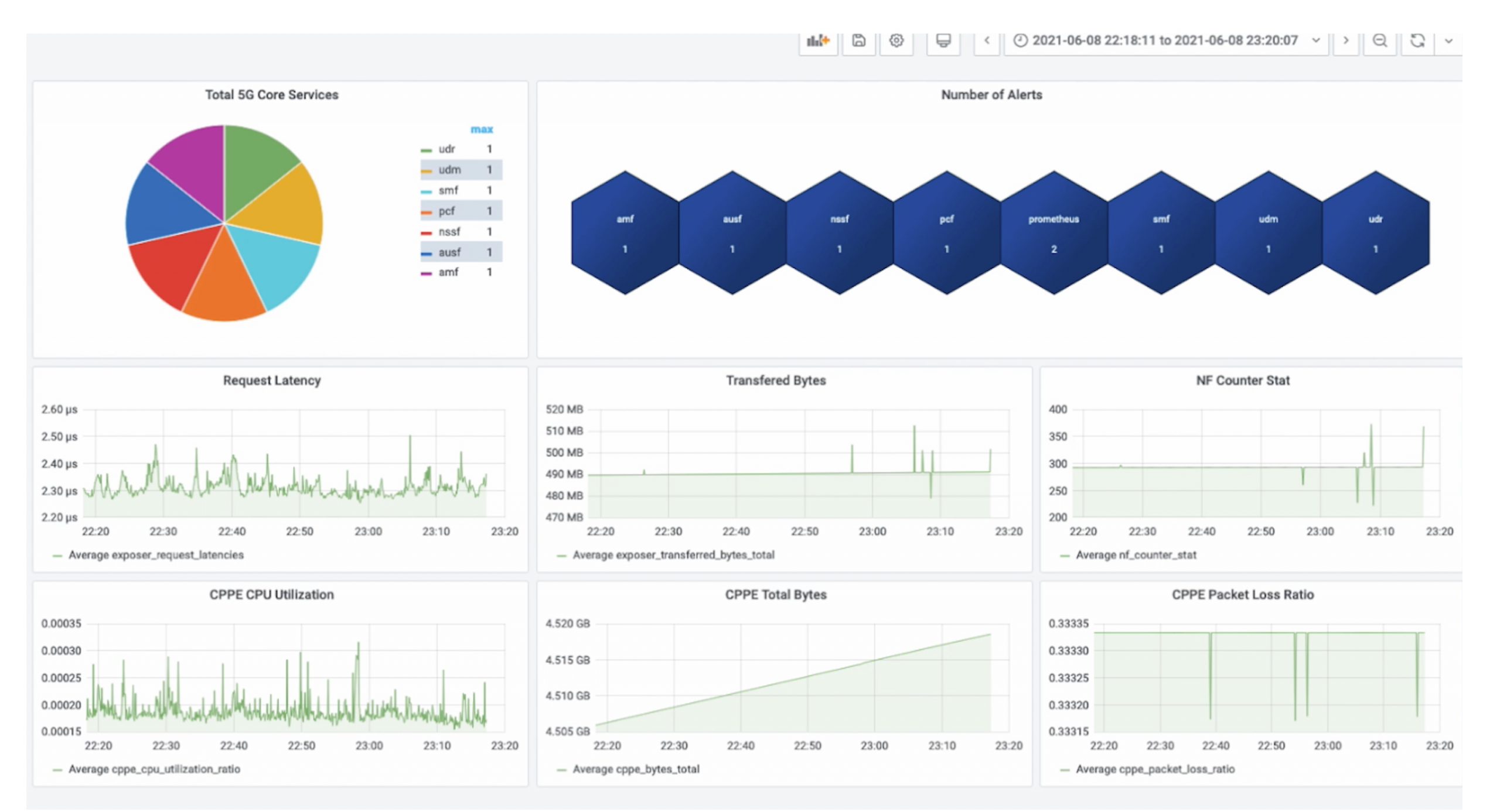
Vmware Unveils Telco Cloud Service Assurance What S New In Release 2 0 And 2 0 1 Vmware Telco Cloud Blog

A Multi Cluster Shared Services Architecture With Amazon Eks Using Cilium Clustermesh Containers

20 Flow Chart Templates Design Tips And Examples Venngage

Addressing Ipv4 Address Exhaustion In Amazon Eks Clusters Using Private Nat Gateways Containers

Diagramming Distributed Architectures With The C4 Model Dev Community

Lean Ux Another Agile Ux Agile Design Thinking Frustration
20 Flow Chart Templates Design Tips And Examples Venngage
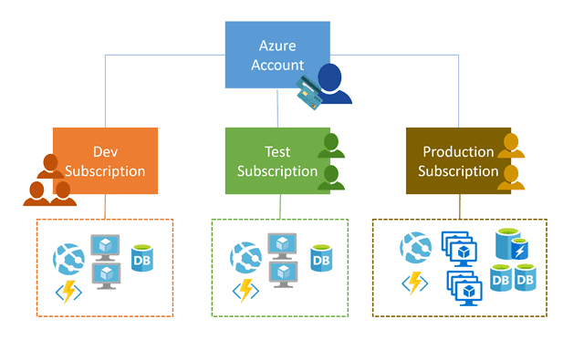
Azure Azure Fundamentals Day 1 Training Az 900

Bundled Load Balancing With Seesaw Anthos Clusters On Vmware Google Cloud